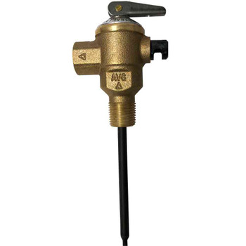
Description
AVG TEMPERING VALVE 15mm with insulation
Yellow Cap rated for Hot Water Storage
plumbonline have have the complete range from AVG (Australian Valve Group) listed online for your seamless selection the full specification is presented for you in clear and easy to read format, if you need assistance get in touch!
Features
The TVA-i (Yellow Cap) is designed for hot water service applications and instantaneous heaters (PLEASE NOTE: Only the High Performance (orange cap) valves are suitable for solar applications.) TVA15CHP valves can also be used in all water heater applications as per TVA installation instructions should you be considering installing a "solar ready" hot water system the valve will be rated for solar use.
- Maximum hot water supply temperature 99°
- More accurate control: ± 3°C from set temperature (to AS4032.2)
- Fast response to pressure fluctuations
- Cast DR bronze body
- Advanced polymer components for greater resistance to calcium deposits
- Integral 60 mesh stainless steel line strainers
- Integral non return valves
- Stainless steel springs
- O-ring seal inlet union connectors complete with nuts and olives
- Tamper proof adjustment
- Special adjusting tool supplied moulded into valve cap
- Seasonal adjustments not required
- Factory set at 50°C (must be commissioned onsite by installer)
- Water Mark Certification – License No. 20137
Valve Specifications
- Valve Specifications (20mm & 15mm TVA’s)
- Cold water supply temperature: 5°C - 25°C
- Hot Water supply temperature: 65°C - 85°C
- Adjustable outlet temperature range: 40°C - 50°C
- Factory set temperature: 50°C nominal (Must be commissioned onsite by installer)
- Accuracy of outlet temperature: ±3°C - tested to AS4032.2
- Minimum temperature differential(between hot supply and outlet temperature): 10°C
- Supply pressure, static : 1600kPa maximum
- Supply pressure, dynamic : 500kPa maximum
- Pressure supply imbalance, dynamic : 2:1 maximum (at time of commissioning )
- Maximum permitted pressure variation in either supply in order to control outlet temperature to ±3°C: ±10 % maximum (from supply pressure at commissioning )
- Flow rate minimum: 4 litres/min
To ensure safety, the TVA must be installed and maintained strictly according to AVG’s installation instructions, Australian Standards and local regulatory requirements. AS3500 now calls on all valves & pipe work to be insulated. AVG provide the insulation & cable ties with the tempering valves
Installation
The tempering valve must be installed by a licensed plumber and in accordance with AS/NZS 3500, relevant local requirements and the following:
- Tempering valve must be fitted in accordance with the instructions supplied with the valve
- It is recommended that isolating valves are fitted immediately upstream of both hot & cold inlets to the tempering valve This allows convenient access to isolate the tempering valve in the event that the strainers need to be cleaned
- It is recommended that the tempering valve be installed as close as possible to the point of use, however it may be fitted anywhere on the hot water supply line.
- If the the tempering valve is fitted at the point-of-use, there must be a minimum one (1) metre pipe run between the valve mixed water outlet connection and the tap
System Supply Pressures
- Tempering valves provide optimum performance when installed with hot and cold water supplies of equal dynamic pressure, ie with the water flowing. (The static supply pressures often give no indication of the dynamic supply pressures). It is recommended that the hot and cold water supplies to each tempering valve be controlled via their own pressure control valve. In most domestic installations it should be possible to fit one control valve at the property boundary to control pressure to the whole site. For commercial installations it is recommended to fit a pressure control valve on each inlet to the tempering valve.
Temperature Adjustment
- Prior to adjusting the tempering valve it is necessary for the hot water heater to be switched on and delivering hot water at the recommended temperature. If the water heater has an adjustable thermostat it is recommended that the thermostat be set to 65ºC. Ensure that the water heater has reached the set temperature before commissioning the tempering valve.
- Test the mixed water temperature at the nearest outlet being supplied by the tempering valve. The tap should be opened to allow a flow rate of at least four (4) litres/minute.
- A thermometer must be used to ensure the correct mixed water temperature is achieved.
- Allow the water to run for at least one minute to ensure the mixed water temperature has settled after each adjustment.
- To adjust the mixed outlet temperature of the tempering valve the cap should be removed to gain access to the adjusting spindle. Using the special tool moulded into the top of the cap rotate the adjusting spindle to achieve the required temperature. The spindle should be rotated - clock wise to reduce the temperature, anti-clock wise to increase the temperature - until the desired temperature is reached. See adjustment diagram provided with the valve.
- Once the required temperature is achieved the cap should be snapped onto the valve to prevent accidental adjustment.
- When the tempering valve has been commissioned, the commissioning label must be completed by the installer and affixed to the water heater in a prominent position, (or other suitable position or as specified by the Local Authority).


